KM155ID1
Dieter's
74141 & 7441 Driver-Tester Project
last update:
November-07-2003 (finished)
Back
to Dieter's Nixie Tube Page
Email
to Dieter
As I have dozens of old "unknown
condition" 74141 and 7441 driver chips laying around. I sat
down and sketched a "super simple" driver- testing
circuit to test them all. I also have russian types and "unknown"
of which I have no idea if they are 74141 or 7441.
REMEMBER!! 74141,
7441 and 7441A are definitely NOT the same!!!
Check the different truth- charts!!!
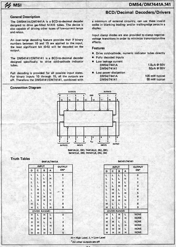
Truth Table for the 74141, 7441,
7441A and 7441B Chip
| Input | 74141 | 7441 | 7441A | 7441B | |||
| D | C | B | A | Output on | Output on | Output on | Output on |
| 0 | 0 | 0 | 0 | 0 | 0 | 0 | 0 |
| 0 | 0 | 0 | 1 | 1 | 1 | 1 | 1 |
| 0 | 0 | 1 | 0 | 2 | 2 | 2 | 2 |
| 0 | 0 | 1 | 1 | 3 | 3 | 3 | 3 |
| 0 | 1 | 0 | 0 | 4 | 4 | 4 | 4 |
| 0 | 1 | 0 | 1 | 5 | 5 | 5 | 5 |
| 0 | 1 | 1 | 0 | 6 | 6 | 6 | 6 |
| 0 | 1 | 1 | 1 | 7 | 7 | 7 | 7 |
| 1 | 0 | 0 | 0 | 8 | 8 | 8 | 8 |
| 1 | 0 | 0 | 1 | 9 | 9 | 9 | 9 |
| 1 | 0 | 1 | 0 | none | see note a | 0 | 8 |
| 1 | 0 | 1 | 1 | none | see note a | 1 | 9 |
| 1 | 1 | 0 | 0 | none | see note a | 2 | 8 |
| 1 | 1 | 0 | 1 | none | see note a | 3 | 9 |
| 1 | 1 | 1 | 0 | none | see note a | 4 | 8 |
| 1 | 1 | 1 | 1 | none | see note a | 5 | 9 |
Note a: For BCD inputs A-F the output alternates between 8&2 and 9&3 illuminated together.
You also have to check all the different 7441 / 74141 drivers types- there are:
| Type | equivalent to |
| 7441 | 7441 |
| 74141 | 74141 |
| 155ID1 | 74141 or 7441 |
| 155ID1 | 74141 or 7441 |
| DM54141 | 74141 |
| DM74141 | 74141 |
| DM74141N | 74141 |
| DM-8640-N | 74141 |
| K155ID1 | 74141 or 7441 |
| KM155ID1 | 74141 or 7441 |
| NTE74141 | 74141 |
| SN74141 | 74141 |
| SN74141J | 74141 |
| SN74141N | 74141 |
| FLL101 | 74141 |
| TL74141N | 74141 |
| DM5441A | 7441A |
| DM7441A | 7441A |
| FJL101 | 7441A |
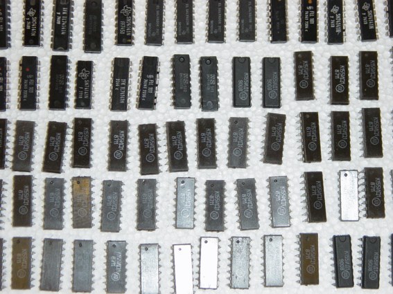
Remenber that te russian
types are marked like this (orange!):
KM155ID1
![]()
![]()
![]()
![]()
![]()
![]()
![]()
![]() or
or ![]()
![]()
![]()
![]()
![]()
![]()
K155ID1
![]()
![]()
![]()
![]()
![]()
![]()
![]() or
or ![]()
![]()
![]()
![]()
![]()
![]()
The
russian types are either 7441 or 74141, high serial numbers are
74141, low serial numbers are 7441.
The russian types have high "off" voltage (approx 100V),
so the efficiency is much better, and the "Blue Spot"
problem can not occur (e.g. IN-18)
I also have some data- sheets for the different types:

Block Diagram for 74141:
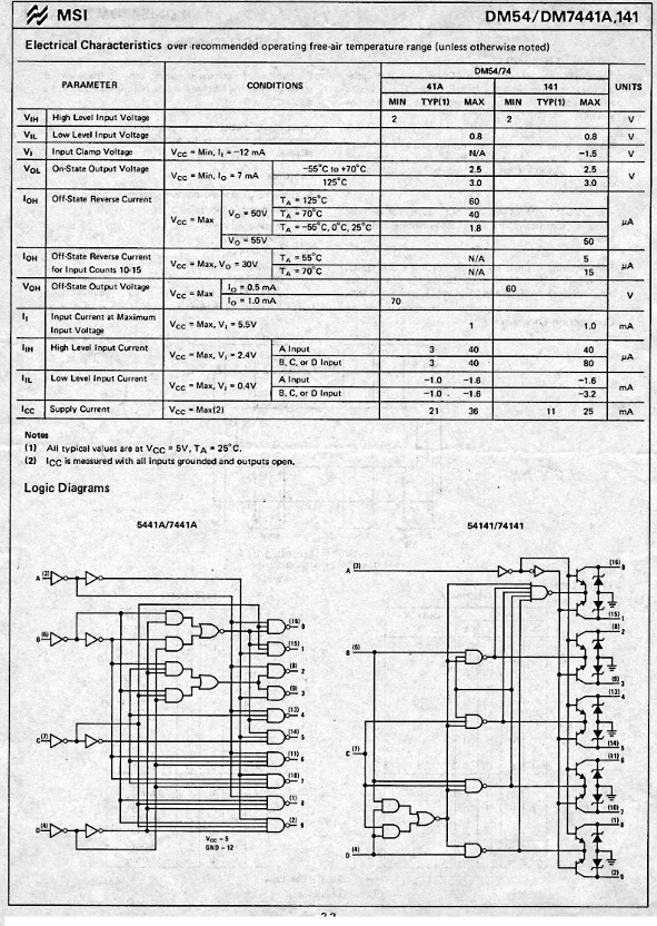
This one I got from Jan:
Ok, lets go to the Sketch I made for my tester
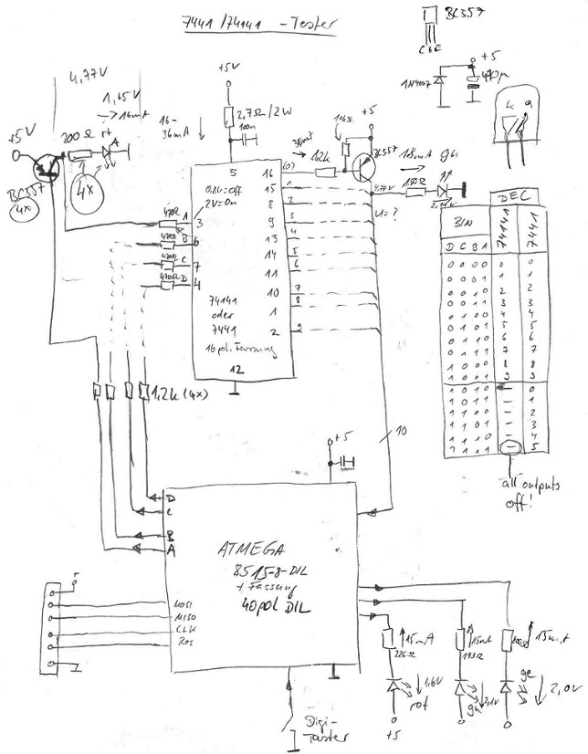
It's so simple,
that there is nearly nothing to explain. Just some words: The 2.7Ohm
resistor provides the over- current protection when the test-IC
is shorted. the controller drives the 4 PNP- transistors- which
drive the control- LEDs ant the inputs of the test- IC. On the
right side you also see 10 transistors which only have the job to
drive the LEDs and the inputs of the controller. I'll use the
very up to date ATmega8515 - so I don't need any reset- circuit,
not even a crystal. The button switch switches between the
different test modes (I'll explain later) and finally the 3 LEDs
show the test results.
The ATmega8515 is totally cool!!! I will use it for all my clocks
in the next future because you need no other parts around it!
There will be a free- running mode:
You only have to put in the test-IC. When the green LED lights up, it's a good 74141. When the yellow LED lights up, it's a good 7441. And when the red LED lights up, the IC is defective.
And there will be a single step mode:
when you hold the button for 1 second, you can switch to the single step mode. there you can check output by output and check (in case the IC is defective) which one is defective and maybe use it for a job where the defective output is not used. When holding the button for longer than one second you come back to the free- running mode.
October-16-2003
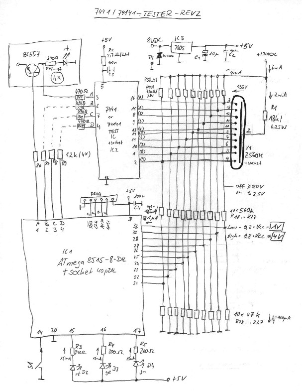
I got many hints from the Neonixies Gang that in some cases a defective 74141 may leak at the outputs. I never took used 74141 (7441) for my project, so I haven't thought about that this also can happen. I had to change my circuit to this second revision, that works with a Z560M. The Z560M tube is driven with 2mA current. the parallel resistors R38 to R47 add 4mA to the switched on output transistor of the test- IC. The 170V (plus tube and resistors) with the voltage dividers make it possible to detect a too high leakage current in case the IC is defective. In this case the voltage at the cathode is lower than 50 volts (I gave the test IC 20% tolerance as you can see) and the inputs of the ATmega are not high (<4VDC). Moreover I have a good control with the tube whether the test- IC really works. I'll need a stabilized 5V voltage to detect the correct voltage level (>4V) at the inputs of the ATmega. So I added a 7805 IC.
Here is the new circuit
October-31-2003
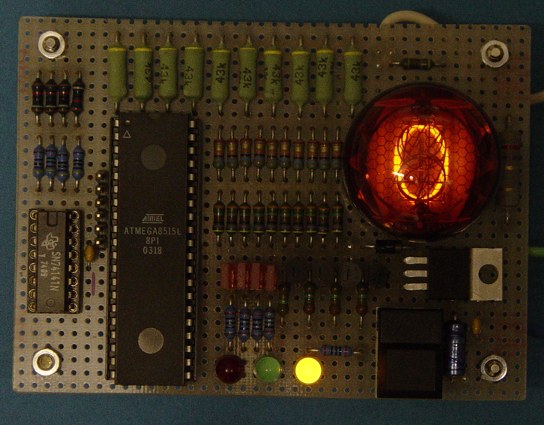
I've finished the board today.
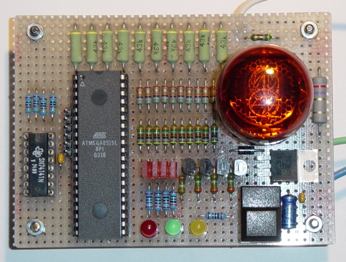
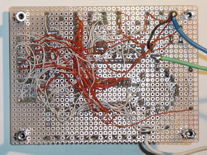
My other projects took away a lot of time, so I decided to give it to a friend of mine to do the coding.
November-07-2003
Operating Instructions
Dieter’s 74141/7441 Nixie Tube Driver Tester
Power Supply
Connect the „GND“- Lead to GND, The +170VDC lead to a
power supply +170VDC and the +8VDC to a power supply 7 to 12VDC.
Operating Instructions
Truth Table for the 74141,7441 and 7441A Chip
Input |
74141 | 7441 | 7441A | |||
| D | C | B | A | Output on | Output on | Output on |
| 0 | 0 | 0 | 0 | 0 | 0 | 0 |
| 0 | 0 | 0 | 1 | 1 | 1 | 1 |
| 0 | 0 | 1 | 0 | 2 | 2 | 2 |
| 0 | 0 | 1 | 1 | 3 | 3 | 3 |
| 0 | 1 | 0 | 0 | 4 | 4 | 4 |
| 0 | 1 | 0 | 1 | 5 | 5 | 5 |
| 0 | 1 | 1 | 0 | 6 | 6 | 6 |
| 0 | 1 | 1 | 1 | 7 | 7 | 7 |
| 1 | 0 | 0 | 0 | 8 | 8 | 8 |
| 1 | 0 | 0 | 1 | 9 | 9 | 9 |
| 1 | 0 | 1 | 0 | none | see note | 0 |
| 1 | 0 | 1 | 1 | none | see note | 1 |
| 1 | 1 | 0 | 0 | none | see note | 2 |
| 1 | 1 | 0 | 1 | none | see note | 3 |
| 1 | 1 | 1 | 0 | none | see note | 4 |
| 1 | 1 | 1 | 1 | none | see note | 5 |
Note a: For BCD inputs A-F the output alternates between 8&2 and 9&3 illuminated together differently.
My friend
did the coding this time (had little time)...
and it works:
All are tested now. I really find some old which
don't work or leak.
I also found out what I wrote above in the section about the
russian tubes.
Note: Please don't ask me for 74141 chips. The ones I have I will use for my next projects.
Project is
finished.
Thanks for reading.
Back
to Dieter's Nixie Tube Page
Go
to Tube-Tester.com
Email
to Dieter
Impressum & Datenschutz
Schlüsselwörter: nixie
nixieröhre nixieröhren röhre röhren tube tubes buizen
indicator numerical vfd vacuum clock nixieclock uhr readout