SP-352 (Beckman)
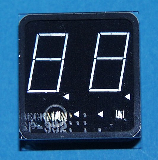
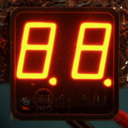
Panaplex Display
Planar neon gas discharge 'Panaplex' readout.
Separate anodes allow single-digit multiplexing.
Used in B&K
282 DMM, Data Precision 3500 VOM, ESE ES-124L clock, Heathkit GC-1005,
GC-1092A & GC-2005 clocks, and Heathkit HW-104, SB-104 &
SB-104A radio transceivers.
| Röhrendaten/Tube Data | |||
| German | English | ||
| Typ | Type | SP-352 | |
| Hersteller | Brand | Beckman | |
| Vergleichstypen | Substitutes | 238-002-9-001, 411-286, 411-0286, 411-295, 411-0295, 1970-0066, EX-352, HB-352 | |
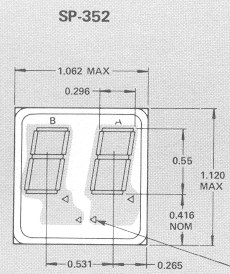
| Symbole | Displayed symbols | 2-Digit, 7 segment, 2 x PR | |
| Symbolhöhe | Symbol height | 14mm (0.55") | |
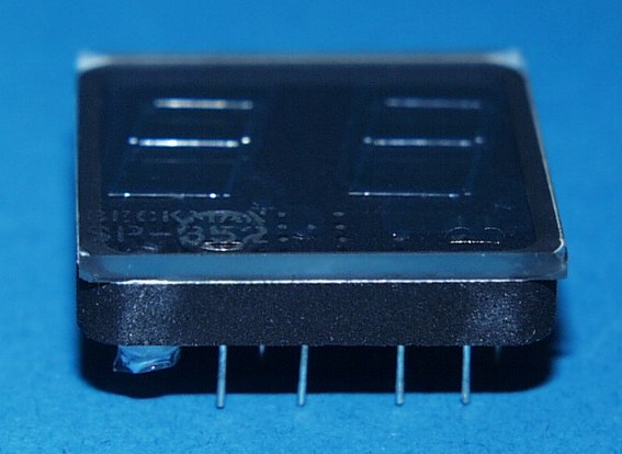
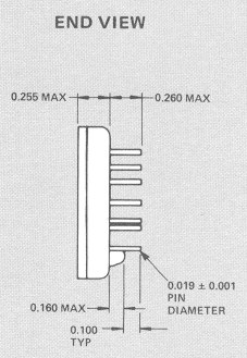
| Abmessungen | Dimensions | 27mm (1.062") X 28.4mm (1.12") X 13.1mm (0.515") thick | |
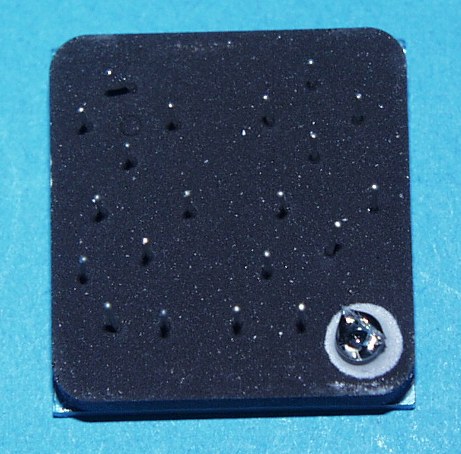
| Pindurchmesser | Pin diameter | 0.48mm (0.019") | |
| min. Betriebsspannung | min. supply voltage | V | 160 |
| typ. Brennspannung | typ. maintaining voltage | V | 135 |
| Betriebs-Kathodenstrom | typ. cathode current | mA |
Siehe Datenblatt für die verschiedenen Segmente!/ See data sheet for different segments! |
| Sockel | Base | 20 pins, special arrangement | |
| Fassung | Socket | Spezielle 20 Pin Fassung/Special 20 pin socket | |
Features:
0.55 Inch (14mm) Character Height (SP-350 Series)
Neon-Orange Color
210 fL Brightness at Nominal Current
130° Viewing Angle
40 ft. (12,2m) Viewing Distance (SP-350 Series)
10 Year Life
DC Characteristics:
|
SP-330 Family |
SP-350 Family |
||||
|
MIN |
TYP |
MAX |
MIN |
TYP |
MAX |
Display Supply Voltage1 |
160 Vdc |
180 Vdc |
Note 2 |
160 Vdc |
180 Vdc |
Note 2 |
Anode-to-Anode
Differential |
--- |
--- |
14 Vdc |
--- |
--- |
14 Vdc |
Anode-to-Cathode
Voltage |
--- |
135 Vdc |
--- |
--- |
135 Vdc |
--- |
Cathode Current -
Typical |
70 µA |
180 µA |
250 µA |
130 µA |
330 µA |
420 µA |
Cathode Current -
Decimal |
60 µA |
135 µA |
190 µA |
65 µA |
135 µA |
190 µA |
Cathode Current- Plus Sign4 |
110 µA |
290 µA |
400 µA |
260 µA |
585 µA |
820 µA |
Cathode Current-Minus Sign4 |
50 µA |
135 µA |
185 µA |
120 µA |
270 µA |
380 µA |
Cathode Current –Keep-Alive |
10 µA |
50 µA |
--- |
10 µA |
50 µA |
--- |
Power Dissipation
(with all segments lighted & |
--- |
175 mW |
--- |
--- |
325 mW |
--- |
Operating Temperature |
0°C |
--- |
70°C |
0°C |
--- |
70°C |
Storage Temperature |
-55°C |
--- |
125°C |
-55°C |
--- |
125°C |
Multiplex Characteristics:
SP-330 Family |
SP-350 Family |
|||||
|
MIN |
TYP |
MAX |
MIN |
TYP |
MAX |
Display Supply Voltage |
160 Vdc |
180 Vdc |
Note 2 |
160 Vdc |
180 Vdc |
Note 2 |
Anode Voltage Swing |
30 Vdc |
45 Vdc |
90 Vdc |
30 Vdc |
45 Vdc |
90 Vdc |
Anode On Time6 7 11 |
80 µsec |
200 µsec |
---- |
80 µsec |
200 µsec |
---- |
Interdigit
Blanking Time12 13 |
40 µsec |
55 µsec |
---- |
40 µsec |
55µsec |
---- |
Refresh Period |
---- |
---- |
Note 6 |
---- |
---- |
Note 6 |
Cathode Voltage Swing8 9 |
30 Vdc |
50 Vdc |
120 Vdc |
30 Vdc |
50 Vdc |
120 Vdc |
Cathode Bias
Voltage (ON |
90 Vdc |
110 Vdc |
120 Vdc |
90 Vdc |
110 Vdc |
120 Vdc |
Notes:
Outline:
Pinout:
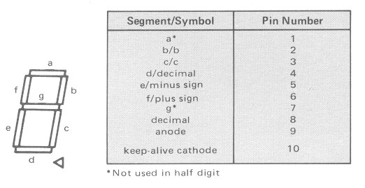
Ansicht von vorne / View from front
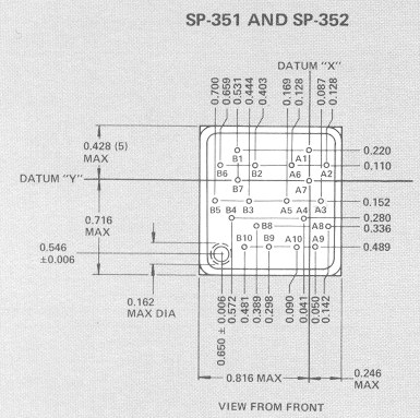
Drawing:
Ansicht von vorne / View from front
Downloads/Datasheets:
Sie finden passende Datenblätter
im Datenblattarchiv.
Suchen sie dort nach dieser Type und deren Vergleichstypen.
You'll find the matching datasheets in
the datasheet archive.
Search for this type and its substitutes there.
Back
to Dieter's Nixie Tube Page
eMail to Dieter
Impressum & Datenschutz