Email to Dieter

This clock-project is based on the 'Beam Deflection Decade Counter Tube' - technology.
See the picture here:

Nocrotec
E1T Clock
(Beam Deflection Decade Counter Tube Clock)
Designed by Dieter
Wächter
last update: February-19-2012
Back
to Dieter's Nixie Tube Page
Email
to Dieter
This clock-project is based on the 'Beam Deflection Decade Counter Tube' - technology.
See the picture here:
What are Beam Deflection Decade
Counter Tubes?
Beam Deflection Decade Counter
Tubes predate Nixie tubes,
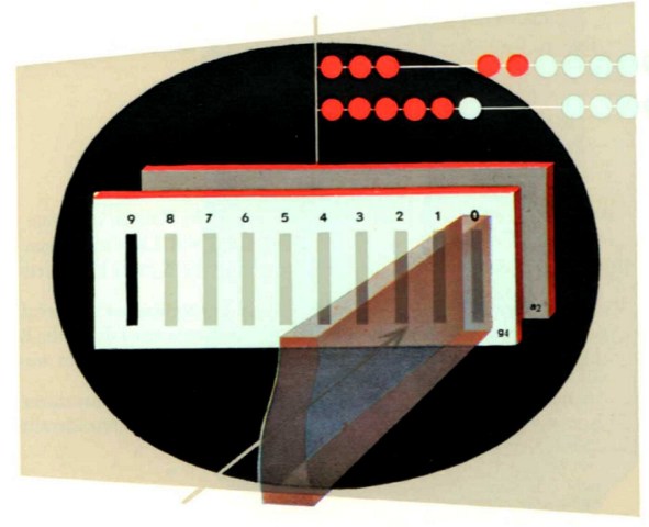
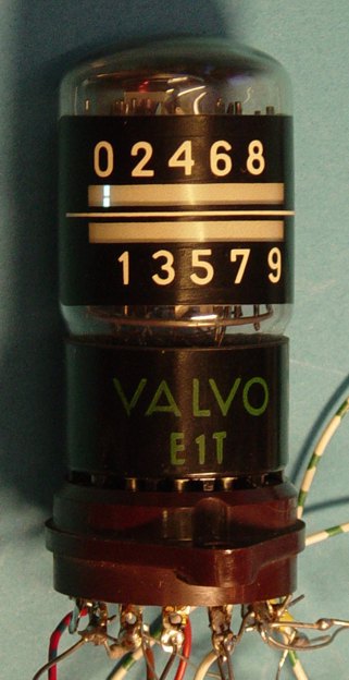
these tiny CRT-like decade counter tubes toggle the position of a brightly lit
blue/green rectangle from one digit to the next with a serial pulse input. They
were used in some early lab counters, and are visually very attractive when lit:

Here you can see an animation of the counting E1T tube:

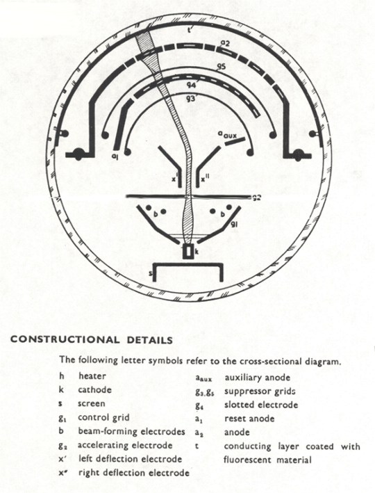
The E1T is an indirectly heated decade counting tube designed to
operate at high counting speeds. A ribbon shaped electron beam is moved in a
horizontal plane and passes in succession through the ten apertures of a
cylindrical anode and impinges on a fluorescent layer on the wall of the tube.
This tube was particularly suitable for use in computers. radiation counters and
industrial counting and batching applications.
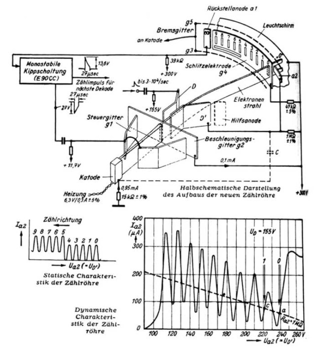
With the standard application circuit shown (see datasheets), the maximum
counting speed is limited to 30 kHz. The tube can be mounted in any position
except with tube horizontal and the fluorescent screen downward. The operation
of this tube can be influenced by external magnetic fields and for satisfactory
operation the flux density of these fields should not exceed 2 gauss in any
direction.
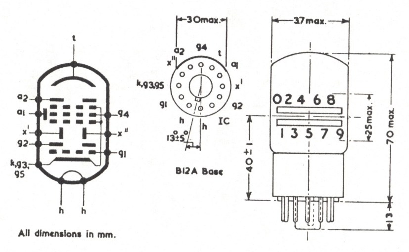
The internal structure is shown in the diagram above.
In order to move the ribbon beam from any one position to the next a pulse of
correct shape must be applied to the left hand deflection plate. The amplitude
of the pulse should have an average value of 13.6 volts and must lie between
11.5 volts and 15.5 volts.
When the beam is moved on from the 9th position it will strike the reset anode
a1. The negative pulse thus produced must be employed to generate two signals,
one to reset the beam to its zero position and another to act as a counting
pulse for the 2nd E1T in the counting chain. The reset pulse is negative going
and is applied to the E1T control grid so that the tube is temporarily cut off.
The minimum amplitude of the reset pulse must be 27 volts. The necessary reset
time is a function of the circuit used and imposes the limit on maximum counting
speed. However, if the reset pulse is too short the beam may return to an
intermediate position instead of to the zero position.
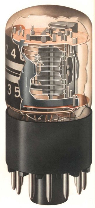
The connections to the base are shown above as is the operating appearance.
The wide glass tube envelope is 38 mm in diameter and excluding the base pins
the valve is 67 mm long.
Pinout & Outline:
Here, at my E1T-tubes page you can
find lots of pictures and descriptions of these tubes.
You'll find the matching datasheets in
the datasheet archive.
Search for this type and its substitutes there.
Now let's go to the development of
the clock:
I really
can tell that it was a mammoth project.
It took about 8 years until it was finished.
But, I only worked some hours a month on that project since in that time I
completed about 60 other projects.
Step 1: Designing the
schematic
After studying the datasheets and some tests on the tube I made some test
circuits:
the timing test board:

The power supply test circuit and the switching supply (the small board is the
switching supply for the 300V/6mA):

Finally I came to this schematic:

As you can
see a complicated design.
I don't have the time to explain the whole schematic, so I will do it in short:
The upper left side shows the mains supply. The primaries are switchable to use
the clock for 115V/60Hz and 230V/50Hz.
It is followed by the switching supply for the 300 V/6mA (done by a boost
converter).
The other voltages are done with regulator circuits.
AVR controller, RTC, the analog circuits and the tubes.
The fist tube can be switched off for the blanking feature.
Step 2: Designing the
board
Also a hard job.
Since all should fit in a flat nice case I used sandwich technology.
This is the result:
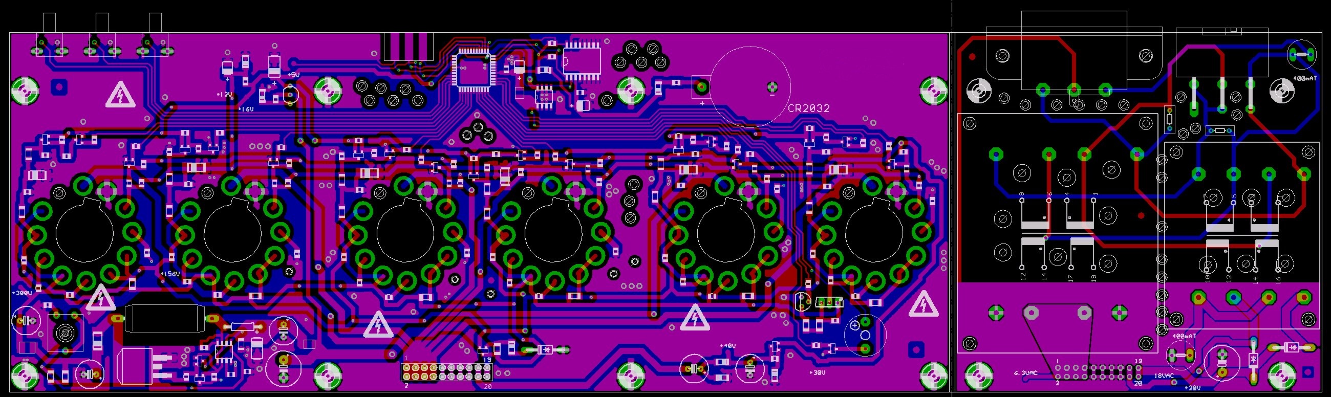
you see the cutting line on the
right.
That means that the board will be cut in 2 parts later, while the right part
sits in the middle of the clock.
Here you see the finished board:
(The main board on the left measures 267 x 102 mm)


Step 3: Assembling the
board
There were no difficulties with the schematic.
Everything worked fine, although it was the first prototype.
The main board bottom side:

The main board top side:

The transformer board top side:

The transformer board bottom side:

The sandwich from the bottom side:

The sandwich from the top side:

Step 4: Designing and
mounting the
case
I made some designs and came to this one (3D-animation only):


Here you see the result of the finished housing:
The bottom plate made of anodized aluminum:


The top, made of beech wood
and acrylic glass:


Here you see the clock
boards mounted in the case:


And finally: the top cover mounted:

Step 6: The coding
The features I put in:
|
Step 7: Mounting tubes
and final test
The clock worked perfect.
Here some impressions:


This
Project is finished
Thanks for reading.
Interested in buying the software package for that clock?
CLICK HERE! (or contact me)
Interested in buying E1T tubes?
CLICK HERE! (or contact me)
Back
to Dieter's Nixie Tube Page
E-mail to Dieter
Impressum & Datenschutz