Dieter's
CD47 Nixie Clock Project
last update: March-22-2005
(stay tuned!!)
Back
to Dieter's Nixie Tube Page
Email
to Dieter
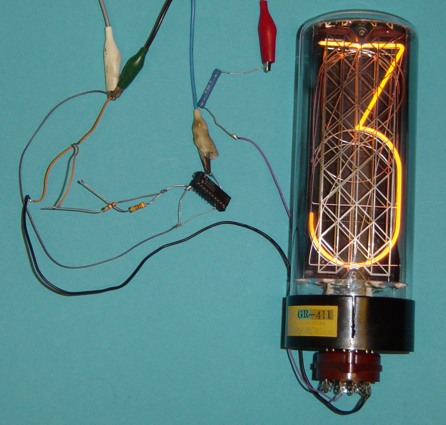
It was in May 2003 when I at last
get some of the very nice Rodan CD47 Tubes.
You can find the technical data and some nice pictures of that
tube here:
CD47/GR-414- Pictures and Technical Data
CD47/GR-411- Pictures and Technical Data
You'll find the matching datasheets in
the datasheet archive.
Search for this type and its substitutes there.
A.J. Franzman also have a nice
gallery of that tube, which you can find here: A.J.'s Gallery
I decided to build a CD47 Nixie
Clock. I thought that it would be interesting for some Nixie
enthusiasts to see the building process. So I statred this site,
which I will update step by step.
Step1: The
Power Supply
For the Power supply I made my
thoughts about the features first. They were:
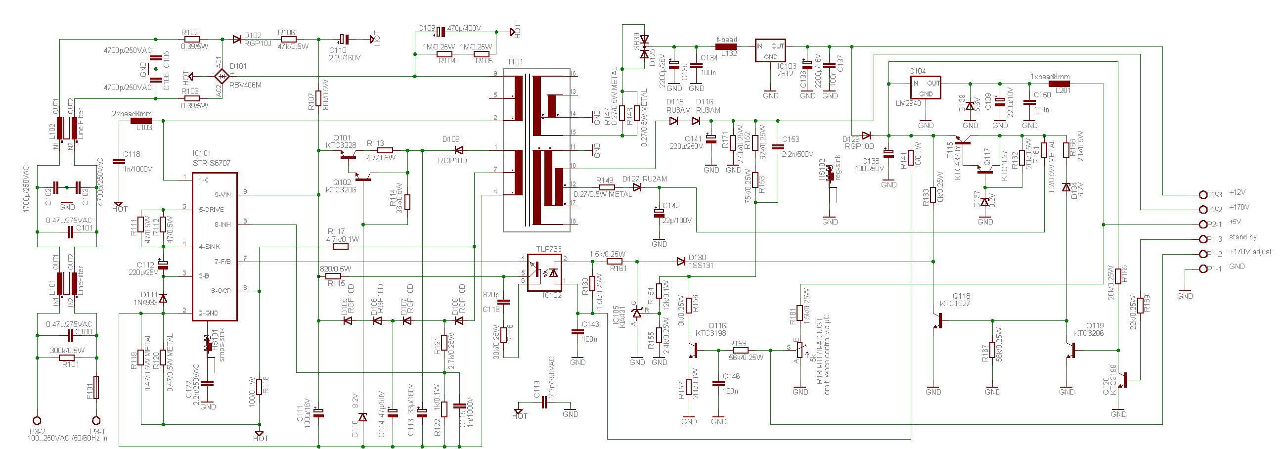
I built up everything around a STR-S6707
switching regulator. You can download it's datasheet.
As you can see there is nothing to adjust, but the output voltage
170V. This can be done by a pot for the test- phase, and later by
the CPU by PWM- modulation. I started this website arter already
made the experiments with the supply, so I unfortunately have no
pictures of the experiments.
The Schematic:
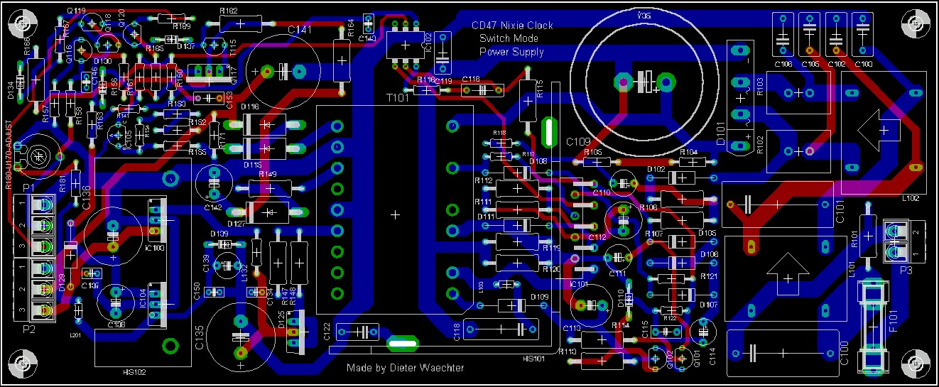
After I built the developing
circuit on a experimental board, I immediately created the real
board (double- sided)
Here you can see
the Layout:
Click on image ot enlarge!
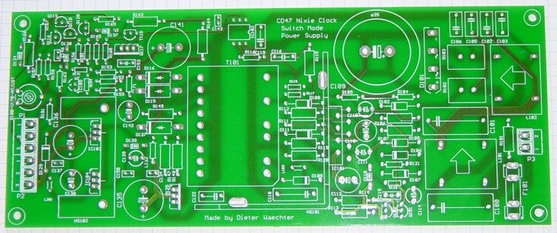
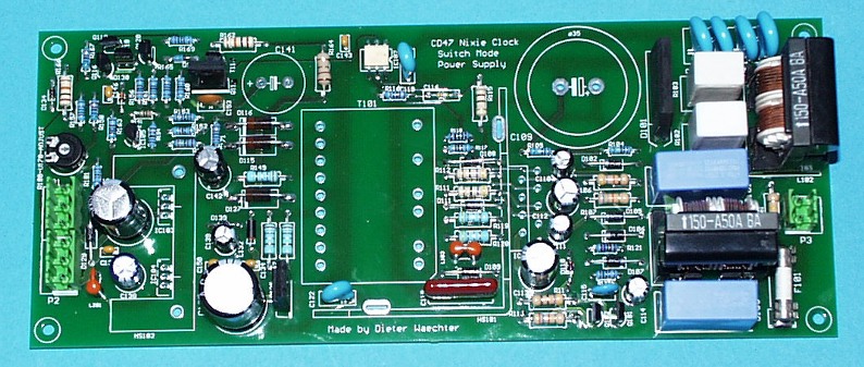
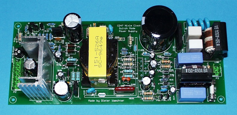
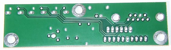
Here you can see the top side of the finished board:
and here the bottom side:
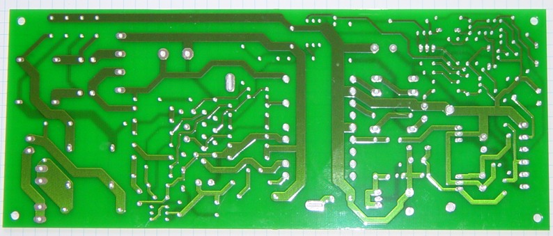
You can see the primary and secondary separation
very well. It remembers a SMPS in a TV-set or PC-monitor.
The SMPS- Partlist:
CD47 Nixie Tube Clock SMPS- Partlist
(klick to display the Partlist)
SMPS- board- equipment:
First I soldered all lower parts (resistors, diodes, ferrite beads.....)

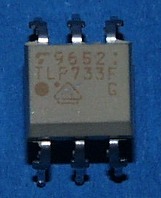
Here you can see the opto - coupler TLP733:
Then I soldered the capacitors, transistors and other parts.
The line filters:
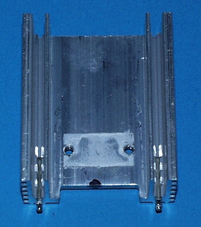
The heatsink for the v-regulators was an old used one (I don't know where I pulled it out):
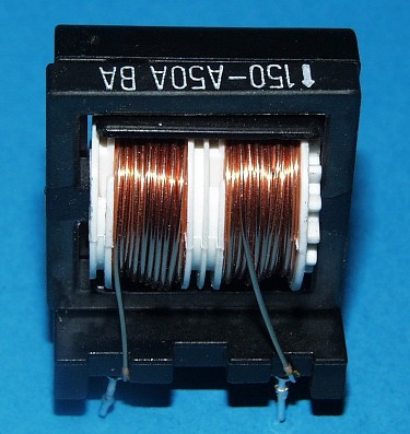
Here you can see the transformer which I pulled out of an old PC-monitor and equipped it so, that it works with the switching regulator:
![]()
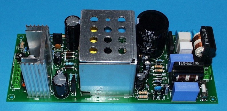
The heatsink for the switching- regulator I took out of an old TV-set (vertical deflection circuit :-):
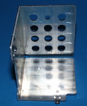
It also works as a screen for the transformer (switching-
pulses!!!):
Peter Stonard @ neonixies asked me to put the eagle files online
for download.
Here
they are

there's little space at the board.
SMPS- Test-
Run:
I made the test- run with a 230V/60W light bulb:
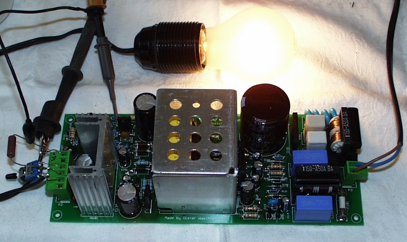
It works like
cream.
The output voltage is adjustable from 160 to 180 Volts by the pot
(later by the CPU). The Stand- By- Mode also works perfect. When
switched to stand by, the 5V- CPU voltage shows no voltage drop,
not even any move of the meter. You can short any output, you can
leave the output open, you can do what you want. It works.
September-21-2003
Step2:
Developement of the ECM- Sonic- Sensor:
The CD47 tubes may be switched on, when a noise
occurs (door opened, TV turned on or something like this). I
developed a simple sonic- sensor with an ECM which will be
connected to the controller (analog input).
I first planned to let it work on the 5V- stand- by- power. But
as I use a radar sensor, which needs 12V to work, I planned a
small DC-DC (5 to 12V) for the Radar- Sensor and for the Acoustic-
Sensor.
The sensor should have the following features:
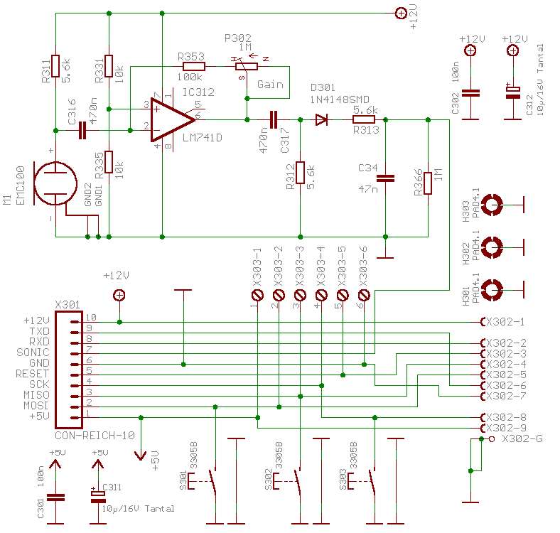
According to this features I developed the following schematic:
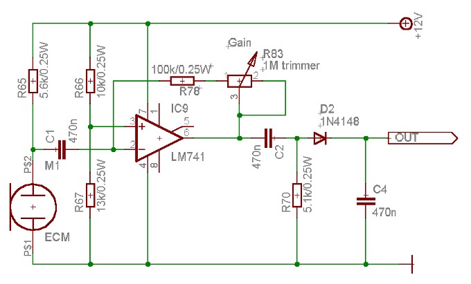
M1 is a standard 2-pin ECM. It's powered by R65.
IC9 is a 741 OP. It works in single supply mode, while the output
is not set to UB/2, but to 7V.
This is for to get only 5V max. at the output.
C1 and C2 are for the AC- coupling.
R83 is the Gain- Pot. (OP is set up to an inverted amplifier, R78
and R83 do the feedback)
R70 is necessary to charge/ decharge C2.
D2 rectifies the pulses.
This schematic may be used for every Nixie- Clock. You don't need a processor. You also can use the output to trigger a longtime- monoflop.
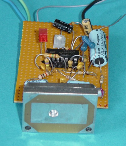
Here you can see how I do my experiments:
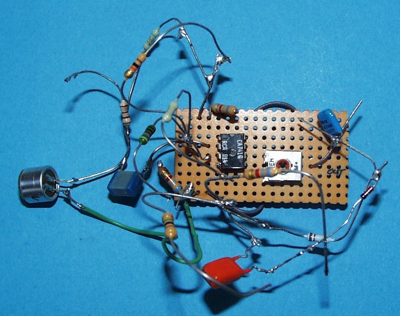
This is not the board I'll use in my clock of course- it's
only an experimental- board. Not nice, but very quick!
October-13-2003:
Step 3: Developement of
the Radar- Sensor- Circuit:
The CD47 tubes may be switched on, when a
movement occurs (door opened, people moving around or something
like this). This I'll solve with a Radar- sensor which will be
connected to the controller (digital input).
The sensor should have the following features:
I've choosen a Siemens KMY24 to meet this conditions.
According to it's appliction notes I used the following schematic:
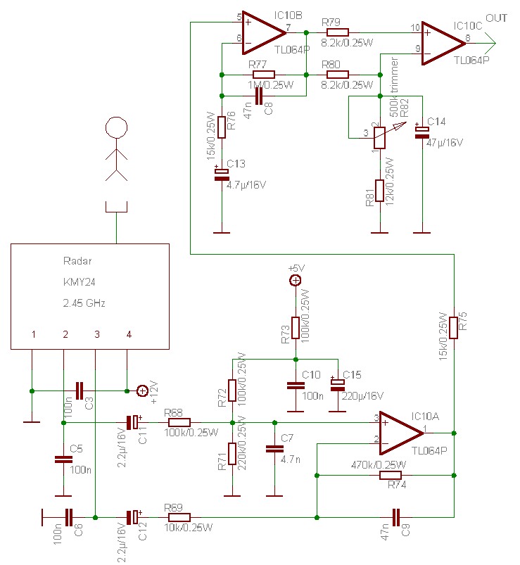
The KMY24 is a radar- sensor which uses the doppler effect. It's simple to use and provides 2 phase- shifted doppler- signals. The signals run through some filters. As you can see, the first OP Stage is a typical differential amplifier. The second stage also a filter, and the third stage is just an impedance-transformer. R82 adjusts the sensitivity. The output provides the 0/5V rectangular signal for the Microcontroller.

This schematic may be used for every Nixie- Clock. You don't
need a processor. You also can use the output to trigger a
longtime- monoflop.
Here you can see the third experimental board (made in just 20
minutes or so- it also will be repalced as soon as the mainboard
is ready, of course):
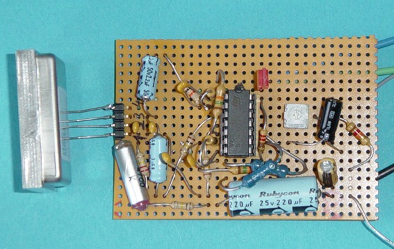
It works very well, and the max. detecting range
is about 7m.
J.C. Wren @ neonixies asked me for the datasheets for the KMY24. Here
it is.
October-14-2003:
Step 5: Developement of the Driver- Circuit:
The CD47 can not be driven by 74141 or 7441 nixie
drivers, because the operating current is to high. So I had to do
it in another way.
The driver circuit should have the following features:
I'll take 8 octal D-type transparent latches type 74HC373 and connect a smd- resistor and a high voltage SMD- transistor to every output- so I get 64 outputs. 60 I use for the cathodes an 4 for the colon- tubes. The colon- tubes are not developed, yet. I made a quick 'rats-nest' experiment, which worked excellent:
So I came to the following simple schematic:

I will get one 8 bid data and one 8 bid adress-
bus... easy to drive with every controller.
When everything would be as easy as this........ ;-)))))
May-30-2004:
Step 6: Developement of the Boards:
After a longer rest I finally found a little time
to develope the Mainboard and the connection- board.
I decided to put the microphone and the ECM- amplifier onto the
connection- board.
I also decided to put a RS232 interface in the clock, so I can
use a DFC77 module or a GPS- mouse or any other time- module or
equipment for the clock.
Here you see the finished schematic of the mainboard.CLICK ON THE IMAGES TO ENLARGE!
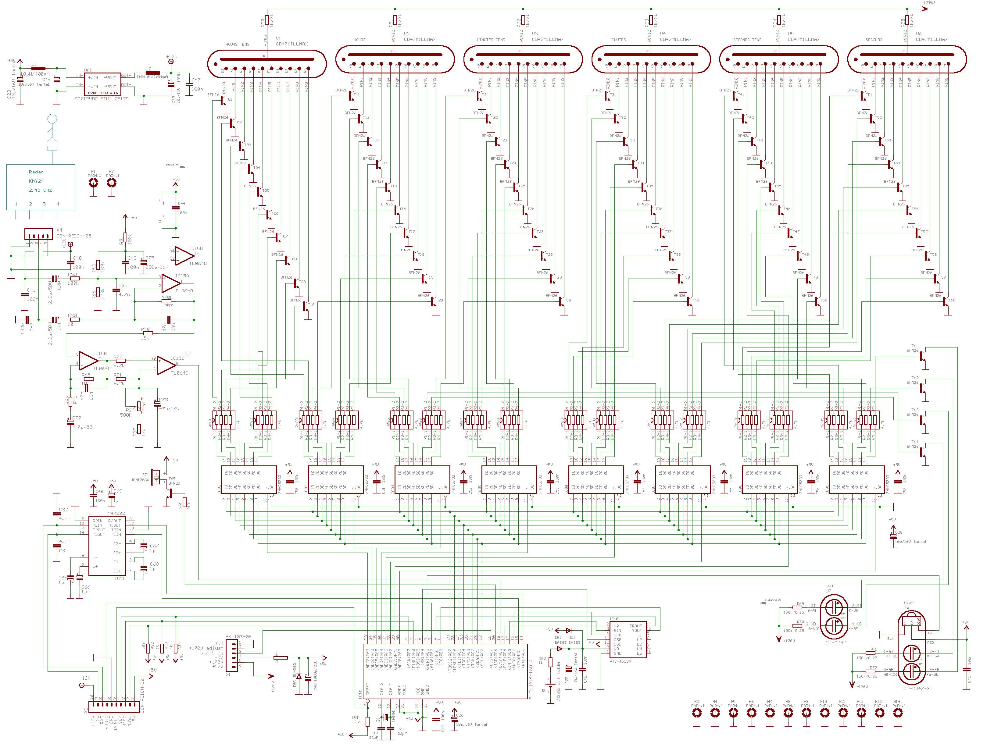
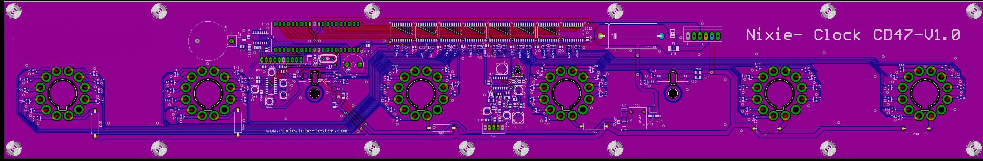
Here you se the finished layout of the mainboard.
It's large. It measures: 600x92 mm!
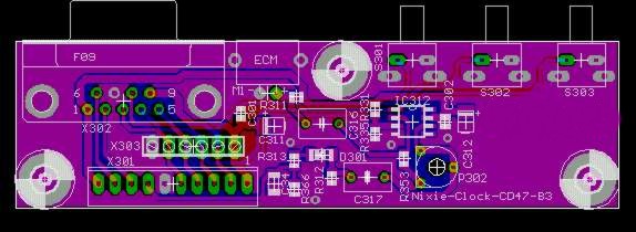
Here you see the finished schematic of the connection- board.
Here you se the finished layout of the connection- board.
March-22-2004:
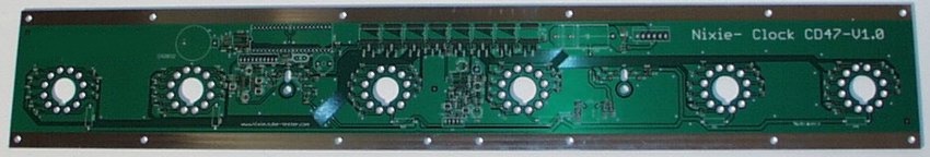
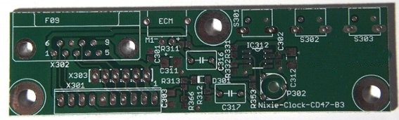
Step 7: The mainboard an the connector board is done!
Finally I had the time to finish the
bare boards.....
Here you see the result.
Check the measurements: 600x92 mm!
The Mainboard:

The Peripheral Board:
Next step will be the bulding of the very special Colon- Tubes
and the board- solderings.
last update: March-22-2005
(stay tuned!!)
TO BE CONTINUED
SOOOOOON!!!!!
Thanks for reading.
Back
to Dieter's Nixie Tube Page
Go
to Tube-Tester.com
Email
to Dieter
Impressum & Datenschutz
Schlüsselwörter: nixie nixieröhre nixieröhren röhre röhren tube tubes buizen indicator numerical vfd vacuum clock nixieclock uhr readout