V600 Nixie Clock
Designed by Dieter Wächter
last update and finished: July-11-2009

Back to Dieter's Nixie Tube Page
Email to Dieter
Watch the video about that clock:
https://www.youtube.com/watch?v=PLPUQcFgIXk
Nocrotec
V600 Nixie Clock
Designed by Dieter
Wächter
last update and finished:
July-11-2009

Back
to Dieter's Nixie Tube Page
Email
to Dieter
Watch the video about that clock:
https://www.youtube.com/watch?v=PLPUQcFgIXk
Here you can watch a second video. This is also a review of the V600-NT from Brian Stuckey (TubeClockdb.com)
(Note: There is a little error in that video, Brian tells the case is aluminum, but it is stainless steel, and will not corrode of course)
https://www.youtube.com/watch?v=C80Avmgvseo
Here you will find the complete review from Brian
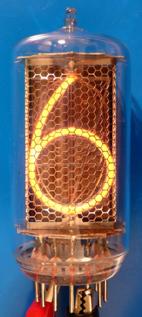
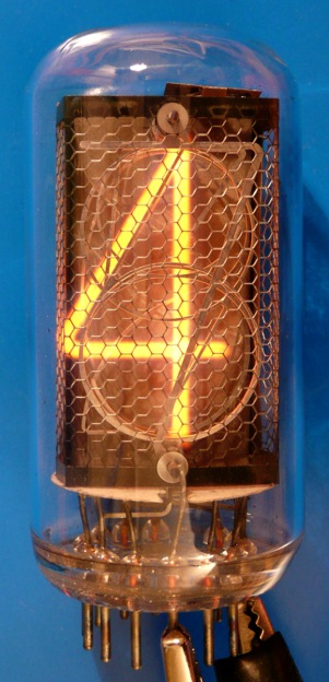
The initial idea of that project was a Nixie tube clock which has a flat shiny
stainless steel case and 6 pcs. 30mm Nixie tubes of the well known Z5660M and
ZM1042 types.
 |
 |
Here you can find the details of that great looking tubes:
| Bilder/ Pictures |
Typ/ Type |
Hersteller/ Brand |
Sockel/ Base |
Zeichen/ Symbols |
ZH mm |
Kurzbeschreibung/ Short Description |

 |
Z5660M | RFT | B13B | 0-9 | 30 | groß, klar und schön!/ large, clear and pretty! |

 |
ZM1042 (Valvo) |
Valvo | B13B | 0-9 | 30 | Die ZM1040/1042 sind die beliebtesten 30 mm Röhren/ The ZM1040/1042 are the most favored 30 mm tubes |
You'll find all technical data about that tubes here at my Nixie Tube Data Archive.
The Power Supply:
The tubes
draw 4.5mA each. So, to total current is 27mA.
You know, I drive all tubes in direct operation, not multiplexed. So I needed a
pretty large supply for that babies.
So the first thing I did was designing a nice quiet and effective switching
power supply.
Here you see the very first test- and improvement-board:

Next step was a self made milled
board for a SMD-circuit in an elongate shape - fitting perfect for the later
clock PCB:
TOP:

BOTTOM:

Note that this is a double sided PCB and was milled at a self made milling
machine.
Many thanks to JR electronics who built this machine and generated the G-code
for the board!
The finished and optimized test board:

It worked perfect for 170V/30mA at 90% efficiency with input voltage 12VDC. This
is very high for a step up converter.
It remains nearly hand warm at full load and works nearly noiseless.
GREAT!
The clock PCB
was the next I designed.
Here you can see the final version of the board:
BOTTOM:

TOP:

the green layer you see here over the tube pin pads is not green grapefruit
jelly but the solder mask, which protects the pads from soldering while the
boards run through the solder wave.
The assembling
could be done now.
The next pictures show the assembled board. The first prototype was hand
assembled and worked perfect.
BOTTOM:
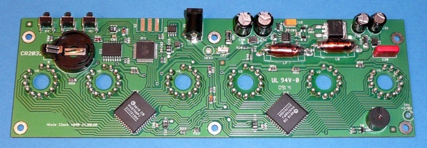
On top right you can see the PSU taken over from the PSU design above with
little changes.
On the top left you see the buttons, the RTC, an ATMEG8515.
On lower side there are the Supertex (Nixie) driver chips for the direct drive.
All in all this super flat board provides a total height of 13mm.
SUPERB!
TOP:

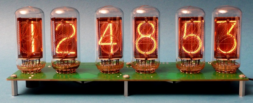
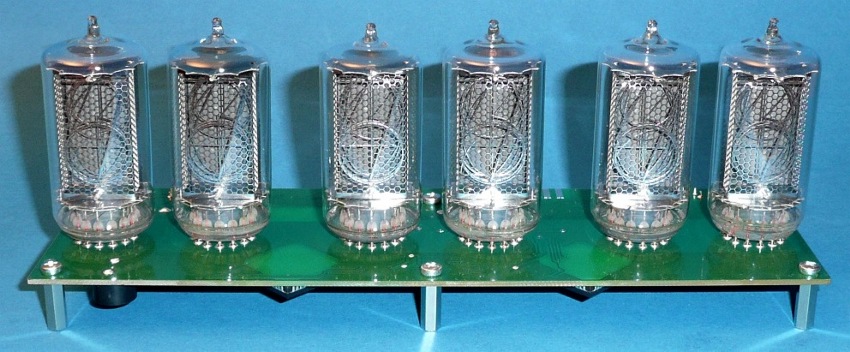
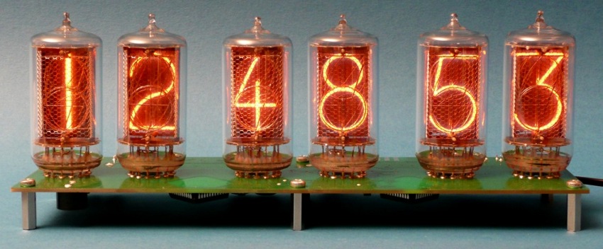
You can see the self made tube sockets here. So the tubes easily can be replaced
and aligned.
The first prototype was born:
With ZM1042 tubes:
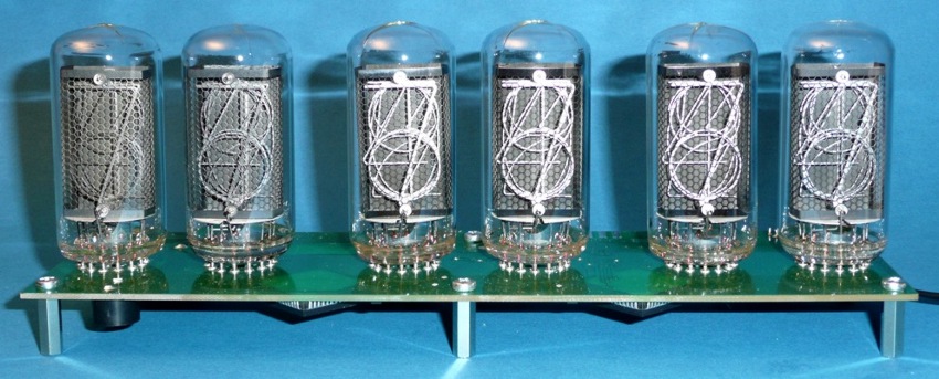
With Z5660M tubes:

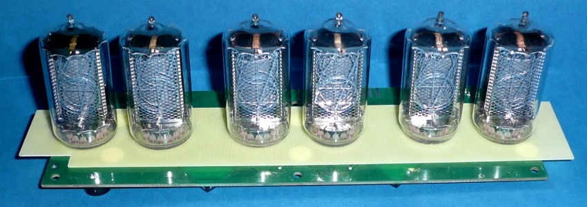
For a
maximum of safety for the user I assembled an insulating plate which protects
the user from the high voltage in case an unauthorized person pulls a tube out
of the clock:


Next step: Designing the
case
I made some designs and ended at this
stainless steel cubic style (first a 3D-animation only)

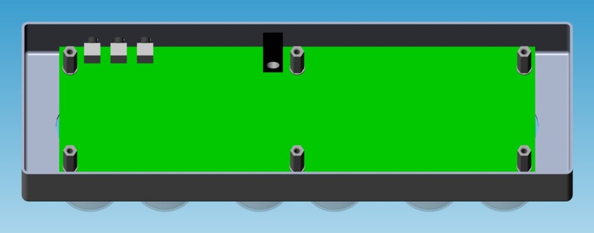

The first prototype case was
done:

It is a laser cut stainless steel sheet, welded
and grind.
The dimensions of the case are: 250 x 80 x 27mm (only!)
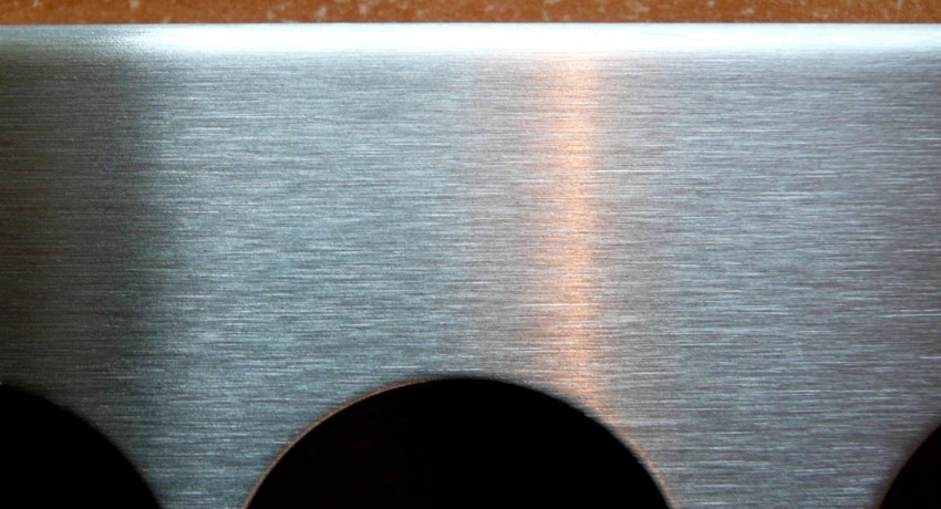
Check out the wonderful surface
finish:

The coding
The features I put in:
|
|
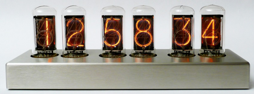
Finally: The result of the finished housing:
With ZM1042 tubes:

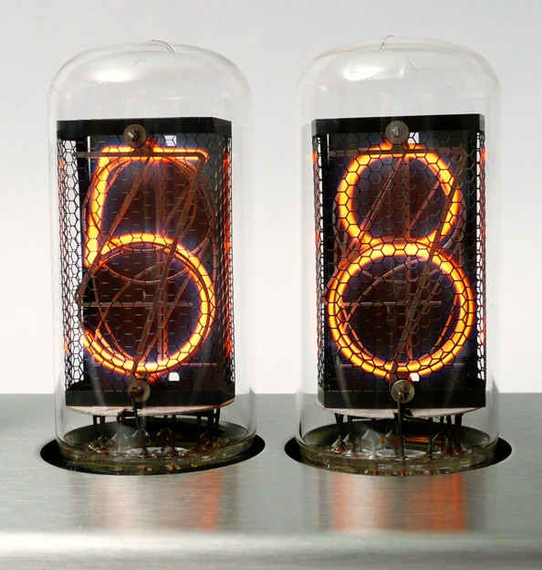

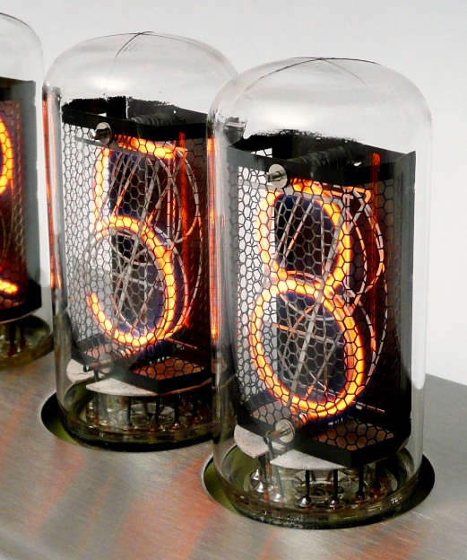
With Z5660M tubes:


The clock at night:


Here you can download the user manual:
Manual Nocrotec V600
Clock
Interested in buying a Nocrotec V600 Clock?
click here!!
This
Project is finished
Thanks for reading.
Back
to Dieter's Nixie Tube Page
eMail to Dieter
Impressum & Datenschutz